A development project using image recognition from a single camera for high speed model vehicle navigation
* Camera must be supported by uvc or pwc and be capable of YUV422 or YUV420P at 320x240x30.
For Linux, you must have a kernel newer than 2.6.26 with v4l and uvcvideo or pwc support.
The controller code for the LPC2148 USB QuickStart Board which can be found here is a modification of the freely available library lpcusb that can be found here. As a result all the instructions to compile that are there, also apply to the modified code. Specifically the virtual serial port example provided with the library, has been changed in the files main_serial.c, adc.c, pwm.c and encoder.c. Doing a make in the directory 'target' or 'examples' will compile everything and produce the file examples/serial.hex that can be used to flash the board.
Detailed instructions on flashing the serial.hex can be found here. The simplest solution is to use the Philips LPC2000 Flash Utility which can be found in a cd-rom that comes with the device package. After connecting the device to your computer using serial follow the instructions below that have been extracted from the above PDF.
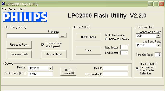
Configure the dialog as shown above. The program will control the RS232 signals DTR and RTS if the appropriate checkbox is checked, and hence provide fully automated program download. You can easily test the connection with a QuickStart Board by pressing the Read Device ID button. The text fields for Part ID and Boot Loader ID will then contain uploaded information from the microcontroller. Observe that the XTAL Freq. must be set to appropriate value. For most QuickStart Boards it’s either 14.7456 MHz or 12.0000 MHz. In these cases the value 14746 or 12000 shall be written in the text box. If the crystal frequency has been changed, make sure the appropriate value is set. Set the communication baud rate to 115200 (for 14.7456 MHz crystal) or 38400 (a reliable connection cannot be achieved with higher baud rates if the crystal is 12 MHz). If no connection can be established test with a low Baud Rate, for example 1200 bps. Also verify that the correct COM-port has been selected (under Connected to Port). Select the HEX file to be downloaded and then press the Upload to Flash button. The downloaded program will immediately start after the download (i.e. the Upload to Flash operation is ready) is the option Execute Code after Upload is checked.
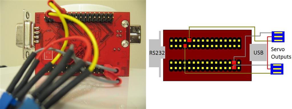
You need two 3 way headers for connecting to the electronic speed controller and the turning servo. Connect the middle pin of both headers together. One header should have the first pin connected to pin 5 on the first socket of the board (starting from 1 and ending at 32) and the third pin to pin 15 on the second socket. Likewise, the other header's first and third pin should be connected to pin 20 on the first socket and pin 31 on the second socket of the board respectively.
On Linux, connecting the board via USB will automatically recognize the device as a usbserial on /dev/ttyACM* using the cdc-acm module. On Windows, drivers can be found in target/examples (the .inf files) of the source file downloaded earlier. The communication protocol consists of sending a string of 9 bytes in the following printf format ">%03d#%03d<" where the two variables represent a value from 060 to 180 (120 is neutral) which control the servo direction. In the case of the speed controller this is the speed (under 120 is reverse, over is forward and 120 is neutral). In the case of the turning servo the same applies for turning left and right. A sidenote is that the device offers protection against going from forward to reverse directly and this action will simply break the car until you go in to neutral and reverse again.
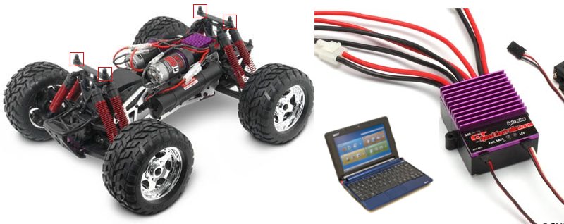
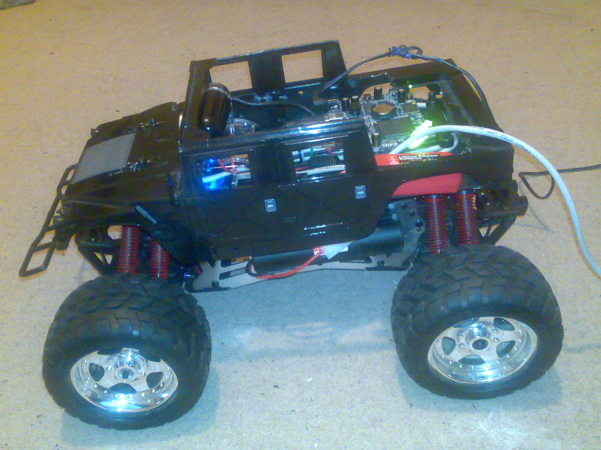
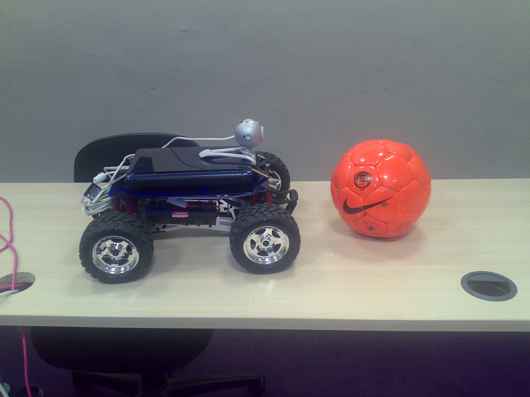
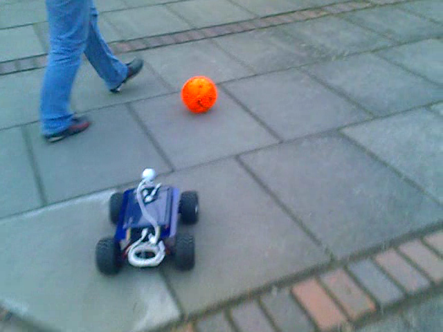
For the purpose of this article we will be using the HPI E-Savage as a base. The first step is to build a base for your laptop. You must choose a suitable base and drill holes where the specified above mounting points will fit. The laptop can be secured on the top using straps. Next is the LPC2148 (controller board), the device responsible for the USB communication to the car's speed controller. It is a good idea to mount this board in the socket that should house the remote control unit for the car. After programming the board and using the wiring diagram described above to connect it to the speed controller's servo lead you simply connect it directly to the mounted laptop through USB. As far as the camera is concerned, it may mounted on the front bumper of the car or alternatively raised above the car using a pole mounted on top of the laptop base.
Colour detection is one of the fastest and most reliable ways of finding known obstacles. With one major flaw, it will only work as well as your camera, histogram and weather conditions. In short, although it is reliable in a controlled enviroment, it is unpredictable if something changes. As such it will not always work on its own. On the bright side there are many things that can be done to improve the robustness of colour detection. The main source of information for colour detection is the histogram. Because of this it must be defined as generic or specific as we need it be. For practical purposes it should be defined as a three dimensional array of 'int'. It should be between the size of 16 and 64 per dimension, as any more would be too specific and memory consuming. You would ideally need two of these, one for the obstacle and one for the drivable surface. It is also a good idea to include functions to dynamically add images to or clear the histograms as well as save and load them. It is a good idea to equalize the histogram to your current situation as well as apply a threshold to the frequency. This will avoid false positives by reducing useless information in the histogram. A good approach in comparing an image against a histogram is to compare each pixel to both histograms, if the pixel appears in both and the difference is small, it should not be taken in to consideration or marked as unknown. In the final step it should be noted that it is a good idea to include features to dynamically alter settings of your camera in order to repair any problems with exposure, brightness, hue, white balance and focus automatically.
In the provided example source, you will find an application capable of following coloured objects such as a bright orange ball. After you have downloaded and extracted the example from here, you may compile the source code by running the relevant compile script named comp_arc in the main folder. Take note that the compile script requires gcc installed and detectable from the PATH. Alternatively, you may run the binary assuming you have a compatible x86 system by running run_arc. As long as you dont have a special configuration it should automatically detect your camera. Similarly you may compile the user interface using comp_ui which requires the java SDK or simply run it by executing local_ui. You may train the software to your object by dragging the area you wish to add to the histogram on the user interface with your left mouse button. Dragging the right mouse button excludes an area from your histogram. Once the blob has been recognised, the software should detect its location on the x axis which can be seen by a small floating cross. If a speed controller is connected to your computer the software will start moving the robot towards the object.
Any questions, suggestions or corrections should be sent to functor_haxdev_org
Simon Lucas, Robin Dowling, Renzo De Nardi and the University of Essex Robotic Car Racing Team
Updated: (PDT)